German
  English
  Arabic
  French
  Italian
  Russian
  Spanish
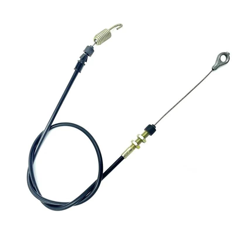
 Push-pull cables are mechanical control components designed to bidirectionally transmit mechanical motion and force between two distinct points in a system via a flexible cable assembly. Their core function is to precisely convert an operating force (push or pull) at one end into linear displacement at the other, enabling remote control.
Functionally, the push-pull cable resolves the challenge of transmitting mechanical energy through complex, curved, or spatially constrained paths. Compared to rigid linkages, it offers exceptional flexibility, allowing easy routing around obstacles. Compared to hydraulic or pneumatic systems, it features simpler construction, lower cost, and independence from external fluid power sources, reducing maintenance complexity in many applications.

Its operational principle can be summarized as follows: A compression force (push) or tension force (pull) applied at the input end is transmitted to the output end via an internal core component that freely slides within a protective outer sheath. This bidirectional transmission capability is its key distinguishing feature from many other cable types, such as Bowden cables that transmit only tensile force.
Push-Pull-Kabelstruktur
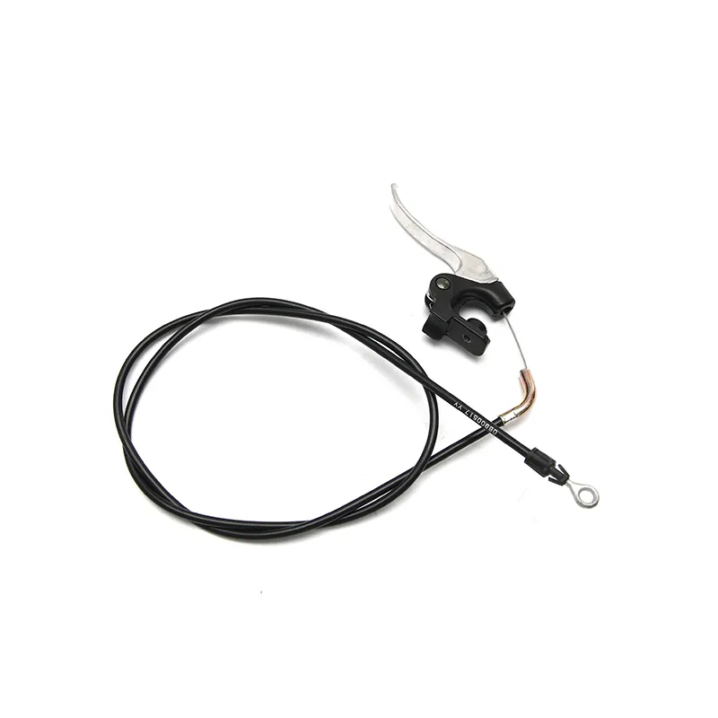
A typical push pull cable system primarily consists of three components: Core/Inner Member, Conduit/Sheath/Housing, and End Fittings.

1. Core
The core is the primary force and motion transmitter. Displacement at both ends closely corresponds within accuracy limits defined by friction, elasticity, and routing.
To balance strength and flexibility, the core typically uses high-carbon steel or stainless steel wire. Stainless steel offers superior corrosion resistance for humid or chemical environments; galvanized steel provides cost-effectiveness.
Cables can be solid, stranded, or armored. For high-performance push-pull cables, core design is critical—it must maintain columnar stability under compression to efficiently transmit thrust. This is typically achieved using solid wires with high Young’s modulus or tightly structured armored cables, while adhering to routing constraints.
2. Conduit/Sheath
The conduit serves as the cable core’s “skeleton” and “track,” fulfilling multiple functions:
- The reaction force support provided by the conduit is critical for enabling the “push” function of push-pull cables. When the cable core is pushed (compressed), it attempts to bend outward. The conduit’s rigid walls provide radial support, constraining the core’s bending tendency and forcing it to transmit pressure axially to the opposite end. Simultaneously, when the cable core is pulled, the conduit bears an equal and opposite compressive force, ensuring overall force equilibrium within the system.
- The conduit provides a smooth, protected sliding channel for the cable core, shielding it from external mechanical damage, abrasion, contamination, and corrosion.
- The conduit’s routing path determines the force transmission route, and its flexibility enables remote control to bypass various obstacles.
Modern high-performance cable tubes typically feature a multi-layer composite structure:
Liner: The layer directly contacting the cable core, usually made of low-friction polymers like polytetrafluoroethylene (PTFE) or high-density polyethylene (HDPE). Its function is to minimize friction resistance during core sliding, enhancing transmission efficiency and operational feel.
Support Layer: This critical layer provides the conduit’s resistance to compression and bending. It consists of multiple high-strength steel wires arranged either parallel along the conduit’s longitudinal axis or spirally wound at a slight angle. These wires impart pressure resistance akin to rigid tubing, ensuring minimal conduit compression and loss of effective stroke under push loads when the cable core is subjected to thrust. In lighter applications, reinforced plastic tubing may be used instead of metallic armoring.
Jacket: The outermost protective layer, usually made of wear-resistant, oil-resistant, UV-resistant, and temperature-resistant plastic materials like PVC, PUR, or TPE. It provides the final environmental protection for the entire cable assembly.
3. End Fittings
These serve as the bridge connecting the cable assembly to operating mechanisms (e.g., handles, pedals) and actuators (e.g., valve arms, clamps). They transmit force and motion into/out of the cable system from external components while securely maintaining the relative positioning of the cable core and conduit.
End fittings come in diverse types including threaded joints, ball joints, fork connectors, and grooved sleeves, customizable to specific installation requirements. The ends of the cable core and conduit typically require separate fixation to ensure only the cable core can move relative to the conduit.
- Threaded Rods:Facilitate precise length adjustment via nuts.
- Ball Joints:Allow angular freedom at the connection point to compensate for misalignment issues.
- Clevis/Yoke Ends:Used for connecting to components like levers via pins.
- Grooved Fittings:Designed for quick snap-in attachment to specific mounting brackets.
Wie funktioniert ein Push-Pull-Kabel?
1. Force Transmission Mechanism: Push and Pull Forces
The fundamental principle behind force transmission in push-pull cables is Newton’s Third Law (action and reaction forces).
Pull Force (Tension) Transmission
When the operating end pulls the cable core, the core is placed under tension. This pull force is transmitted directly to the actuating end through the cable core. Simultaneously, the entire cable tube experiences an equal and opposite compressive force—because the end fittings at both ends of the cable core “pull together” the tube’s ends. Due to the high compressive strength of the tube’s support layer, it effectively resists this compression, ensuring the tensile force is transmitted with minimal loss (ignoring friction). In this mode, the push-pull cable functions similarly to a standard steel wire rope, operating with high efficiency.
Push/Compression Transmission
This represents the core principle of push-pull cable design. When the operating end pushes the cable core, it experiences compressive force. Theoretically, a slender flexible rod subjected to compression would rapidly fail due to Euler buckling. However, within the push-pull cable, the core is tightly enclosed within the conduit. When the core attempts to bend, it bears against the conduit’s inner wall, which provides continuous lateral support and delays global buckling. Within the manufacturer’s rated limits, this allows the compressive force to be transmitted predominantly axially to the output end, although the conduit and its supports experience a combination of axial, radial, and bending reactions, and the allowable push load is lower than the allowable pull load. In this process, the conduit’s compressive strength and the clearance between the cable core and the conduit’s inner wall are critical factors determining the push force transmission capacity. The smaller the clearance and the stiffer the conduit, the greater the push force the cable core can transmit, resulting in improved system “rigidity.”
In summary, push-pull cables ingeniously leverage a “separate functions, distinct roles” design philosophy: the inner core specializes in transmitting axial forces (pull or push), while the conduit focuses on providing counter-support (compression or tension) and constraining the core’s motion. This synergy between inner core and outer sheath enables a flexible component to combine rigidity and flexibility, achieving efficient bidirectional force transmission.
2. Mechanical Interaction Between Core and Sheath: Friction and Lubrication
The interaction between core and sheath is not idealized frictionless sliding; friction is a core factor affecting push-pull cable performance.
Sources and Effects of Friction:
1.Sliding Friction
Friction generated when the cable core slides against the cable tube lining. It directly consumes input energy, reducing transmission efficiency. Friction increases with transmitted load and bend severity, so higher working loads and tighter routing typically produce higher friction losses.
2.Bending Friction
When the cable bends, the core presses tightly against the inner wall of the outer sheath on the bend’s outer side, generating additional normal pressure that dramatically increases friction. This effect becomes more pronounced with smaller bend radii and greater bend angles. This explains why both design and installation emphasize using the largest possible bend radius.
3.Static vs. Dynamic Friction
When a system transitions from rest to motion, it must overcome substantial static friction. This causes an unresponsive feel and “stick-slip” behavior. Once motion begins, dynamic friction is slightly reduced. The negative impacts of friction are multifaceted: reduced efficiency (output force < input force), generation of backlash, wear on the cable core and inner lining, and uneven operating forces.
Backlash Generation:
Gap created by cable deflection and friction in bends, also termed “empty stroke” or “dead travel,” is a critical performance metric for push-pull cables. It consists of two primary components:
1.Mechanical Clearance:The physical gap between the cable core and the inner wall of the cable tube. When the direction of motion reverses (e.g., from push to pull), the cable core must traverse this gap before re-engaging with the tube wall to transmit force.
2.Friction Clearance:This arises from friction along the bending path. When the cable core is pushed, it travels along the “longest path” (outer side) of the bend; When pulled, it attempts to follow the “shortest path” (inner side). Switching between these two paths results in stroke loss.
Lubrication Mechanism:
Lubrication is crucial to counteract friction. Modern push-pull cables typically employ multiple lubrication strategies:
1. Self-lubricating liner: Using materials with inherently low friction coefficients, such as PTFE or HDPE, as the liner is the most fundamental method to reduce friction.
2.Permanent Lubrication:During manufacturing, long-lasting grease specifically formulated for cables is injected into the cable tube. These greases feature high adhesion, wide temperature ranges, and excellent wear resistance, providing continuous lubrication throughout the cable’s lifespan with minimal maintenance. Some designs incorporate microscopic grooves or ribbed structures on the liner surface to store grease, ensuring sustained lubrication.
3.Sealing Protection:Efficient end seals and robust outer jackets prevent external contaminants (water, dust, chemicals) from entering the cable interior. Once inside, contaminants mix with lubricant to form abrasive pastes or cause internal component corrosion, drastically increasing friction and leading to premature cable failure. Maintaining internal cleanliness is therefore critical for sustaining low friction.
Push-Pull Control Cable Using Case
1. Automotive Industry Applications
In the automotive industry, push-pull cables were once a primary method for connecting driver inputs to vehicle actuators. Despite the growing prevalence of electronic controls, mechanical push-pull cables retain a place in many applications due to their reliability, intuitiveness, and cost-effectiveness.

Throttle Control Systems
In conventional (non-electronic throttle) vehicles, the throttle cable represents one of the most classic applications of push-pull cables.
- Operating Principle:When the driver depresses the accelerator pedal, the pedal’s lever mechanism pulls the throttle cable (inner core). The other end of the cable connects to the control arm of the throttle valve plate on the engine’s intake manifold. The displacement of the inner cable precisely translates into the rotation angle of the throttle valve plate, thereby controlling the airflow into the engine and regulating engine speed and power output. When the driver releases the accelerator pedal, the return spring on the throttle body pulls the valve plate closed while simultaneously pushing the throttle cable (inner cable) back to its initial position.
- Design Features: Automotive throttle cables demand high responsiveness and precision. Consequently, low-friction designs—such as PTFE linings—are commonly employed to ensure smooth, snag-free throttle operation. To enhance driving comfort, some throttle systems incorporate dampers that absorb impact and noise generated when the throttle body snaps back during rapid release.
Clutch and Transmission Control
In manual transmission vehicles, push-pull cables are also commonly used for clutch control and gearshift control.
- Clutch Control: When the driver depresses the clutch pedal, the push-pull cable pulls the clutch release fork to disengage the clutch.
- Transmission Control: The shift lever in the driver’s compartment connects to the transmission’s gear selection and shifting mechanisms via two or more push-pull cables. The driver’s actions of pushing, pulling, or rocking the shift lever are translated into the precise pushing and pulling movements of multiple cables, enabling accurate gear engagement within the transmission.
2. Industrial and Mechanical Control
In industrial applications, push-pull cables serve as the “workhorse” for remote manual control of heavy equipment and automated processes.
- Construction Machinery:On excavators, loaders, rollers, and similar equipment, push-pull cables control hydraulic valve spools to manipulate working components like booms and buckets. They also govern engine throttle and shutdown functions.
- Agricultural Machinery:On tractors and combine harvesters, they control clutches, throttles, hydraulic lifts, and similar systems.
- Marine Control:Employed to regulate engine throttles and gear shifts on vessels. Marine push-pull cables demand exceptional seawater corrosion resistance and waterproof sealing.
Remote Valve Control: In chemical plants, power stations, and similar facilities, they enable remote opening or closing of valves located in hazardous or inaccessible areas.

3. Other Application Areas
- Bicycles:Bicycle brake and gear shifting systems represent one of the most widely recognized applications for push-pull cables (typically pull cables in this context). Riders pull the cable by squeezing brake levers or shifting shifters, thereby actuating brake calipers or derailleurs.
- Medical Devices:In certain medical instruments requiring precise remote manipulation, miniature push-pull cables control the working head at the end of an endoscope or surgical instruments.
- Furniture:Adjustable recliners, sofas, and similar furniture often use push-pull cables to control the release mechanisms for backrest angles or footrests.

About SCOJET
As a professional manufacturing service provider, we specialize in offering customized push-pull cable solutions tailored to the specific needs of various industries. Our existing custom push-pull cable projects include, but are not limited to, wheelchairs, road rollers, snow blowers, bicycles, lawn mowers, etc.
Contact us today for your exclusive customization services!